A while ago I built something slightly unusual: a complete Wi-Fi receiver in which no human wrote a single line of the hardware. An AI assistant read a MATLAB reference design and generated the entire receive chain as a digital circuit. It runs on an ADALM-Pluto, a USB-powered software-defined radio with a fingernail-sized FPGA. Fed a standard Wi-Fi waveform produced by MATLAB’s own toolbox, it recovers the transmitted image byte-for-byte.
That last sentence is where the real question lives. If no engineer wrote the circuit, why should anyone believe it is correct? A radio that mostly works is worthless; the bits are either right or they are not. This post is about the answer: a generation method where every layer proves itself against the one above it, so trust comes from the structure of the process rather than from anyone’s assurance.
The reference design
MATLAB ships a reference example called Image Transmission and Reception Using 802.11 Waveform and SDR. It is a full 802.11a link: take an image, slice it into packets, modulate them into a Wi-Fi waveform, send it over the air, then synchronize, equalize, and error-correct on the receiving end until the original image comes back intact.
I had wanted to put that receiver onto an FPGA for years. The obstacle was never the idea; it was the labour. Porting it by hand, translating MATLAB line by line into hardware description code and then verifying the result, is tedious enough that I kept finding reasons not to start. So the project sat untouched until our generation framework matured enough to try a different approach: let the AI start from the same reference and produce the receiver directly.
A few days later, the entire receive chain existed as synthesizable hardware.
Generating hardware in checkable layers
The method’s whole value is that it does not generate one opaque blob of code. It builds the design in three layers, and machine-checks each layer against the previous one.
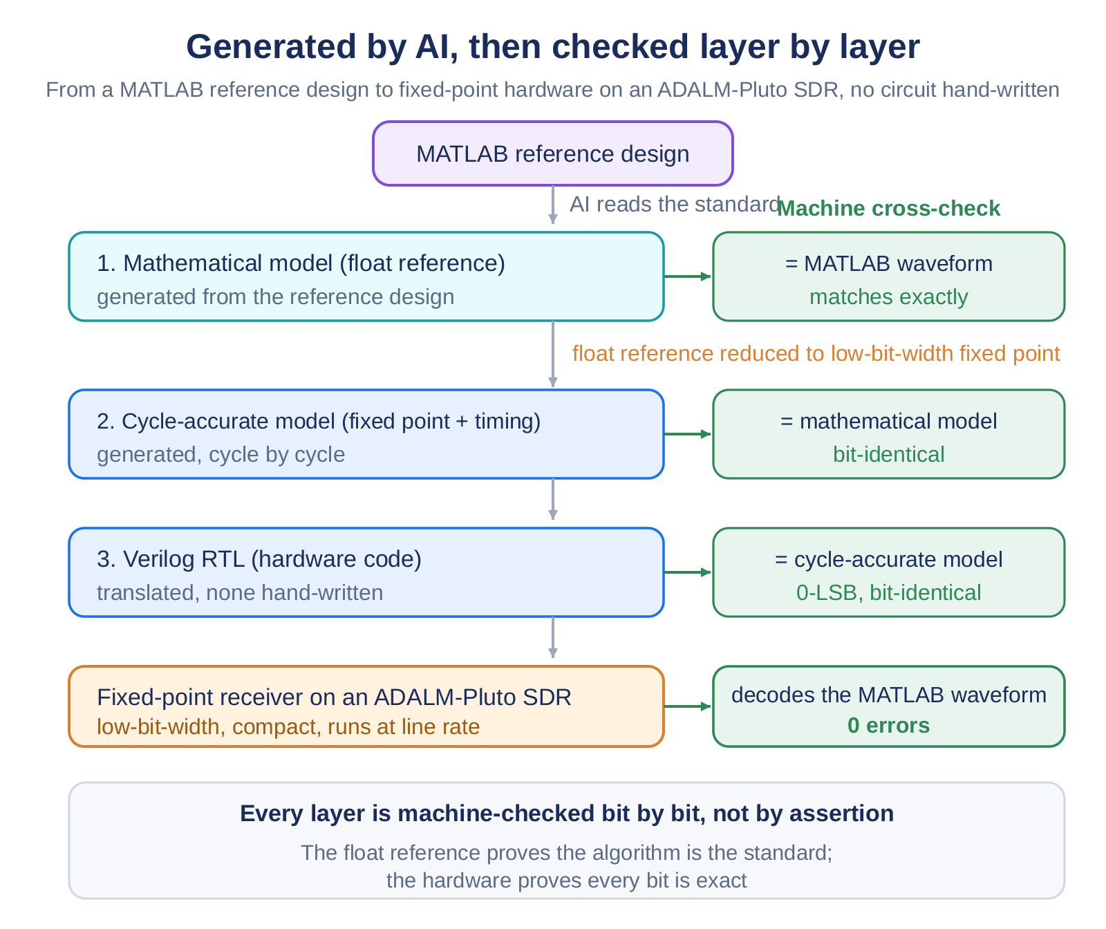
- A math reference is generated first: a plain, floating-point model of the algorithm. Its output matches MATLAB’s standard toolbox waveform exactly, which pins down what “correct” means.
- A hardware-timed model comes next: the same algorithm, but now in the narrow fixed-point arithmetic a chip actually uses, with the cycle-by-cycle timing of real hardware. A machine checks that it matches the math reference, value for value.
- The circuit is generated last, and a machine checks that it reproduces the hardware-timed model with zero difference.
The point worth dwelling on: between each adjacent pair of layers, the agreement is verified automatically, not asserted by a person. And there is one honest subtlety. A chip using narrow fixed-point arithmetic can never match a double-precision reference down to the last decimal, so demanding that would be meaningless. The real test is simpler and stricter: feed in a standard signal, and every recovered bit must be correct.
What the receiver actually does
What arrives at the receiver is not an antenna signal but a stream of baseband samples, already digitized by the radio’s RF chip. The job is to turn that stream into clean data bits, following the same steps as the MATLAB reference.
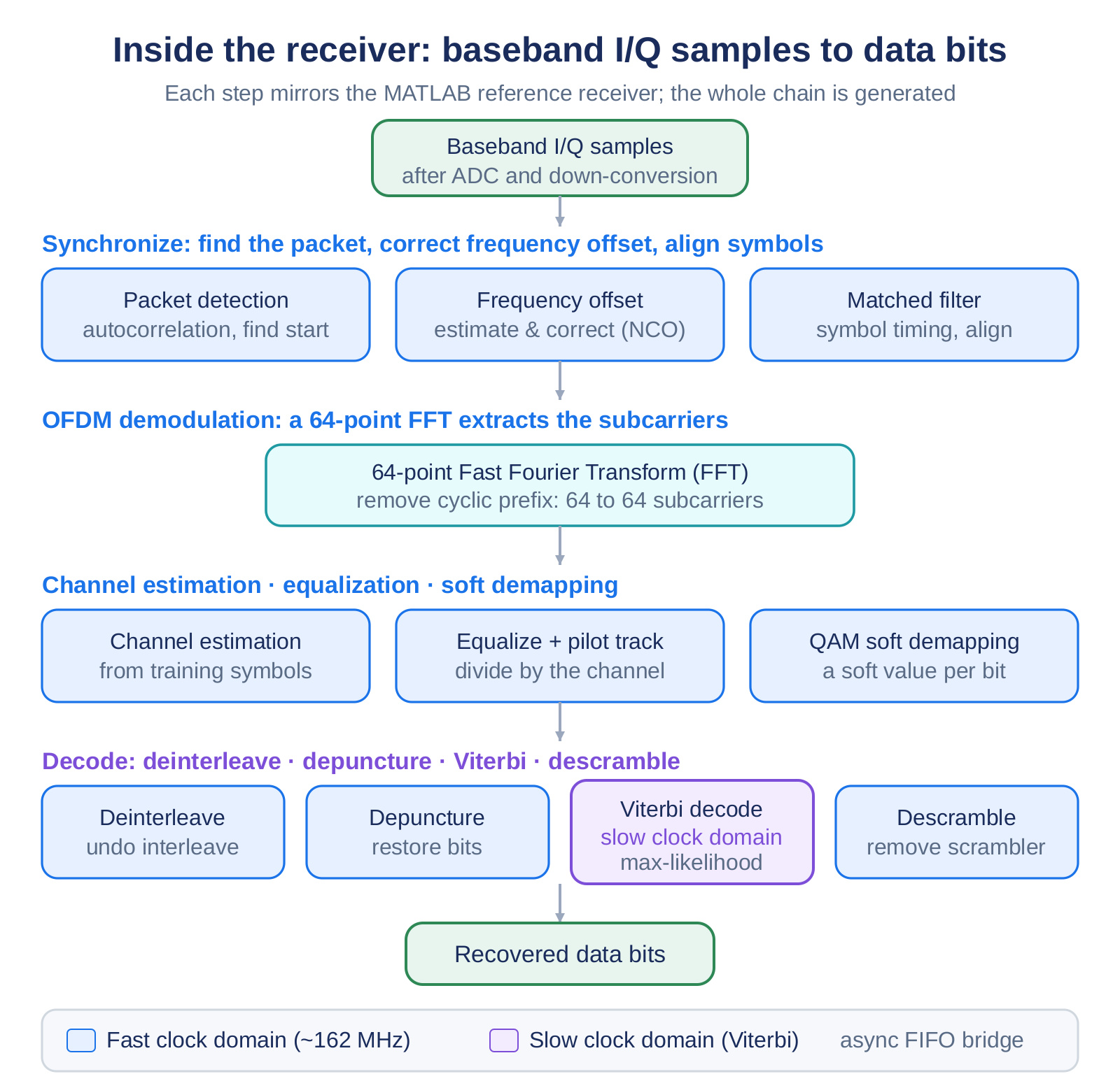
The chain has four stages: lock onto the start of each packet and correct its frequency offset; strip the cyclic prefix and transform each symbol into its subcarriers; estimate the channel and equalize, then turn the constellation points into bit confidence values; and finally de-interleave and run a Viterbi decoder for maximum-likelihood error correction. It runs continuously, accepting a new sample on a fixed cadence and never needing to stop. The Viterbi decoder is the one piece that cannot be hurried, since it is a feedback loop, so it lives in a slower clock region and hands data across a safe boundary to the rest of the design.
One image, sent and recovered
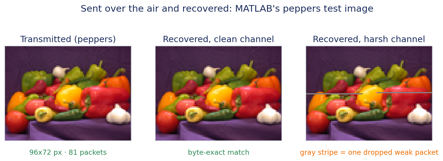
The reference design’s finale is to send a whole image across the link. I kept its classic test photo and changed only one thing: the receiver is now the generated hardware.
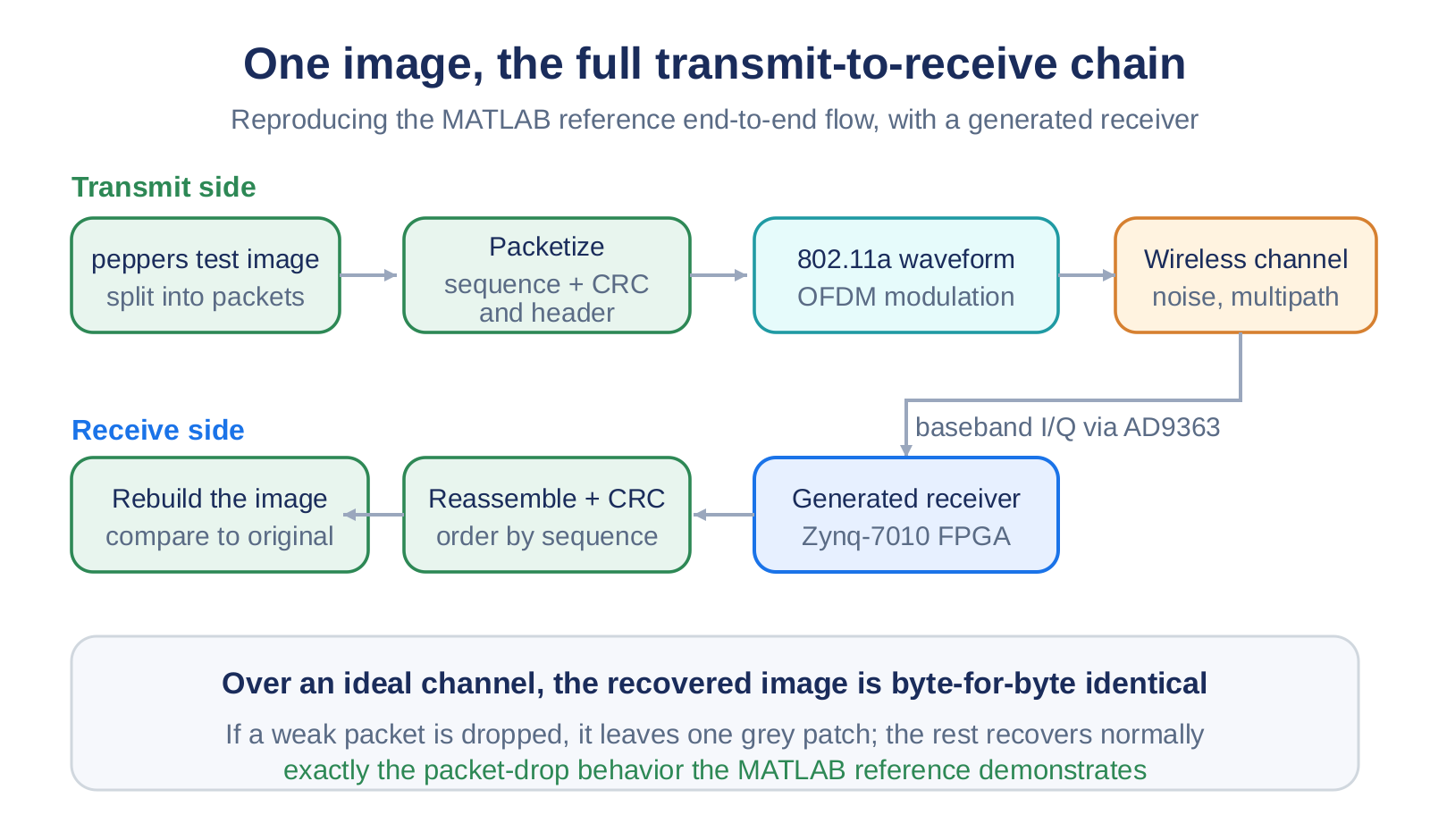
Over a clean channel, the recovered image is identical to the original, byte for byte. To show the system behaving honestly under stress, I deliberately drove one packet’s signal level far down. Its integrity check fails, that packet is dropped, and the reconstructed image carries a single grey band where it went missing while everything else comes back perfectly. That is exactly the packet-loss behaviour the reference design demonstrates, now running on a circuit nobody wrote by hand.
Checking against an independent standard
A demonstration is persuasive, but the strongest check uses an outside authority. In wireless, that authority is MATLAB’s WLAN Toolbox, which implements the 802.11 standard directly. The comparison happens at two levels, and it matters that they are kept separate.
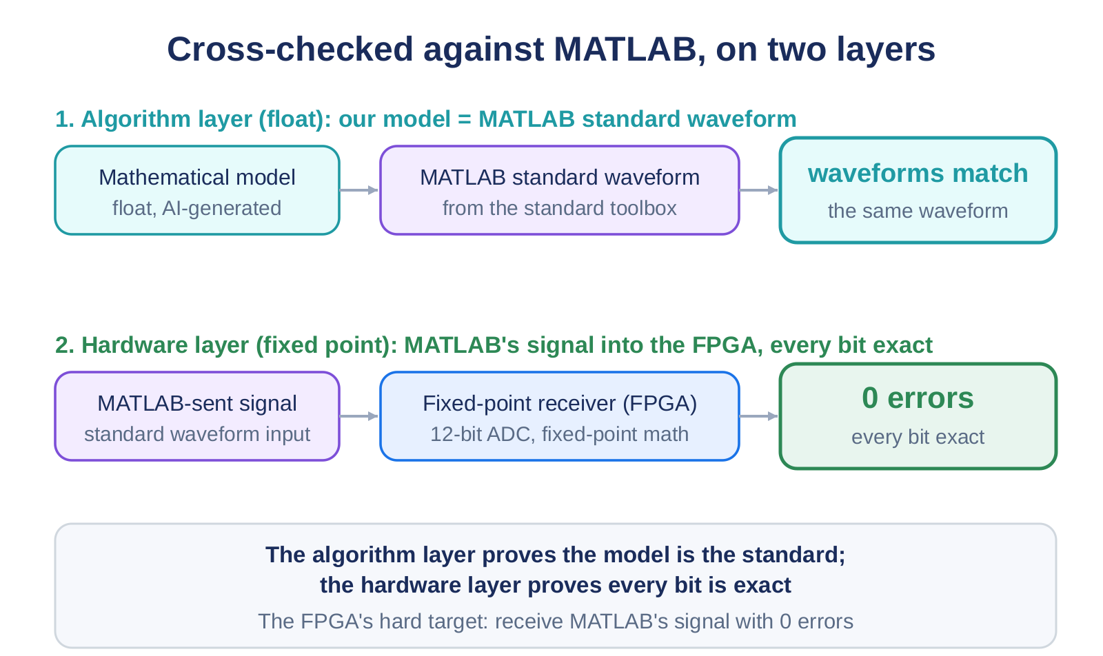
At the algorithm level, the generated floating-point reference is compared sample by sample against waveforms from the standard toolbox. They coincide, which says the reference is the standard. At the hardware level, MATLAB becomes the transmitter: it generates standard waveforms, those are quantized as a real receiver would see them, and fed into the fixed-point circuit. Every bit comes back correct. This is the most convincing step precisely because the transmitter is an independent, standards-compliant tool, not something I wrote.
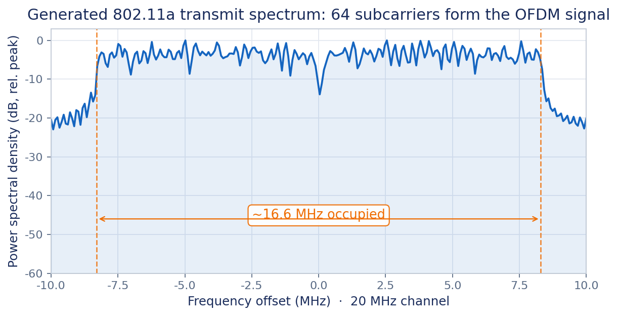
What the signal looks like
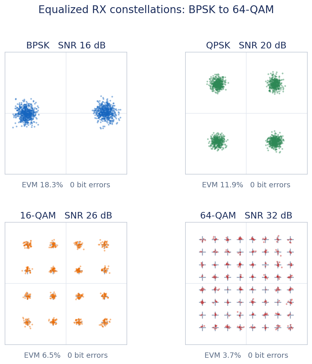
It is also worth looking at the signal itself. These are not illustrations; they are measured by running real waveforms through the fixed-point receiver.
The constellations show the receiver across modulations, from the robust scheme that survives the weakest signals to the dense one that packs the most bits per symbol and demands the cleanest channel.
Sweeping signal quality across the full range traces out the familiar error-rate curves: the robust modulation clears errors at low signal levels, the dense one needs much more. Together they mark the honest boundary of where this receiver works.
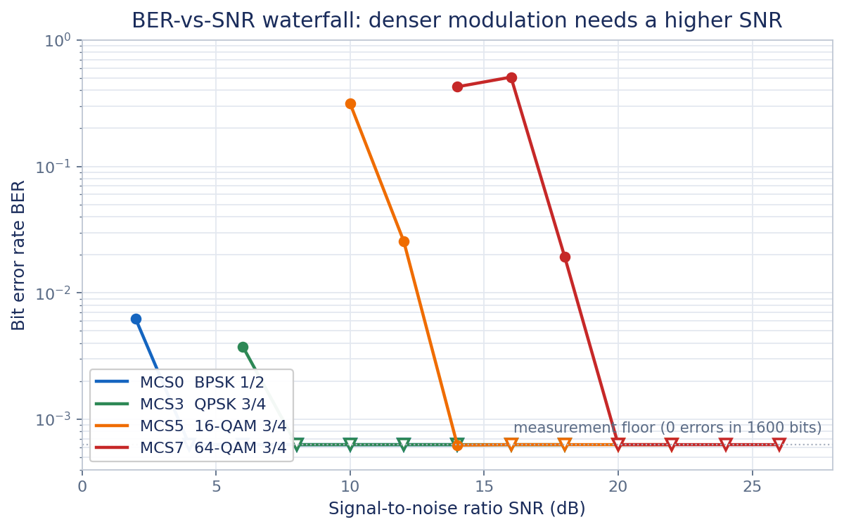
Every modulation and coding combination in the standard decodes correctly through the complete hardware, including under a harsh multipath channel, and all of it on a board that a developer can hold in one hand.
Why this generalizes
I built a Wi-Fi receiver, but nothing in the method is specific to Wi-Fi. From the mathematical definition, to the hardware-timed model, to the circuit, each layer is provably equivalent to the one above it, and that equivalence is checked by a machine rather than promised by a person. The receiver happens to be made of ten such modules, each verified on its own.
The reusable result is not this one radio. It is the discipline underneath it: a way of generating hardware in which every layer always knows exactly what it is supposed to match. The hand-written port I avoided for years took an AI a few days, and the signal MATLAB sent came back without a single bit out of place. That is the part worth keeping.