A Viterbi decoder is the error-correction block at the end of almost every Wi-Fi, LTE, and satellite link. The hard part was never decoding. It is fitting the decoder onto a cheap, small FPGA, or packing several of them onto one chip. Underneath, that is a resource problem: spend fewer lookup tables, fewer flip-flops, less on-chip memory.
The hardware for this decoder was not written by hand. It was generated from a Python description of the algorithm by our generation framework. This post is about what came next: handing it to an AI to optimize for resources. The AI worked the way an FPGA engineer does - it read the place-and-route utilization and timing reports, decided where the savings were and which moves could reach them, measured each result, judged right from wrong, backed out of a dead-end, and verified every change bit-for-bit. The reusable result is not this one decoder. It is that loop.
What a Viterbi decoder actually does
It helps to picture the algorithm before talking about what is expensive in it.
Think of a layered road map. Each layer has a handful of junctions, and you want the lowest-total-cost route from start to finish. At every junction you keep only the single cheapest way to reach it and discard the rest. When you arrive at the end, you walk backwards along the routes you kept, and the best overall path falls out. That is exactly what a Viterbi decoder does.
Back in radio terms: a convolutional code adds redundancy to each transmitted bit, and the receiver gets a stream of noisy soft samples. The decoder works backwards from that noise to the most likely sequence of bits that was actually sent - maximum-likelihood decoding.
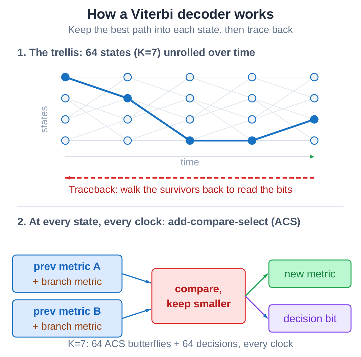
That map is called a trellis. With constraint length seven, it has sixty-four states - sixty-four junctions. Every clock, each state runs one add-compare-select: add the branch cost, compare the two incoming paths, keep the better one, and record which it chose. After enough decisions accumulate, walking backwards from the current best state recovers the bits one by one. That last step is the traceback.
Why shrinking it is hard
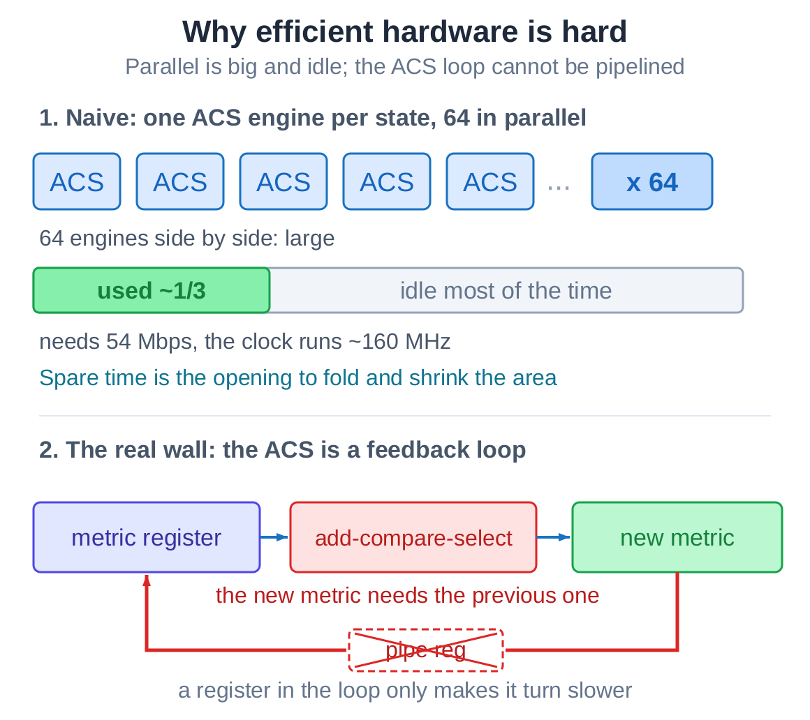
The most direct build gives all sixty-four states their own add-compare-select engine, sixty-four side by side, finishing a step every clock. Fast and simple, but large and wasteful - and idle most of the time, because the throughput an application needs is far below what the FPGA can run.
The harder problem is in the add-compare-select itself. The new path metric depends on the one just computed a clock earlier. That is a feedback loop, and a feedback loop cannot be sped up by pipelining: the next step needs this step’s result, so dropping a register into the path only makes the loop turn slower. So “can folding save area” and “can folding keep the clock” are two separate questions. That separation is the whole difficulty.
So why fold at all? Because the application never needs full speed. The fastest 802.11a mode is 54 Mbps, while a full-speed decoder running at 160 MHz emits one bit per clock - about 160 Mbps, nearly three times the requirement. That headroom is the opportunity: time-multiplex the compute. Let one engine run a few clocks and take all the states in turn, instead of laying down a wide field of fully parallel hardware. As long as throughput stays above 54 Mbps nothing is lost, and everything saved is area. The only remaining catch is not to drop the clock while folding.
The first lever: folding
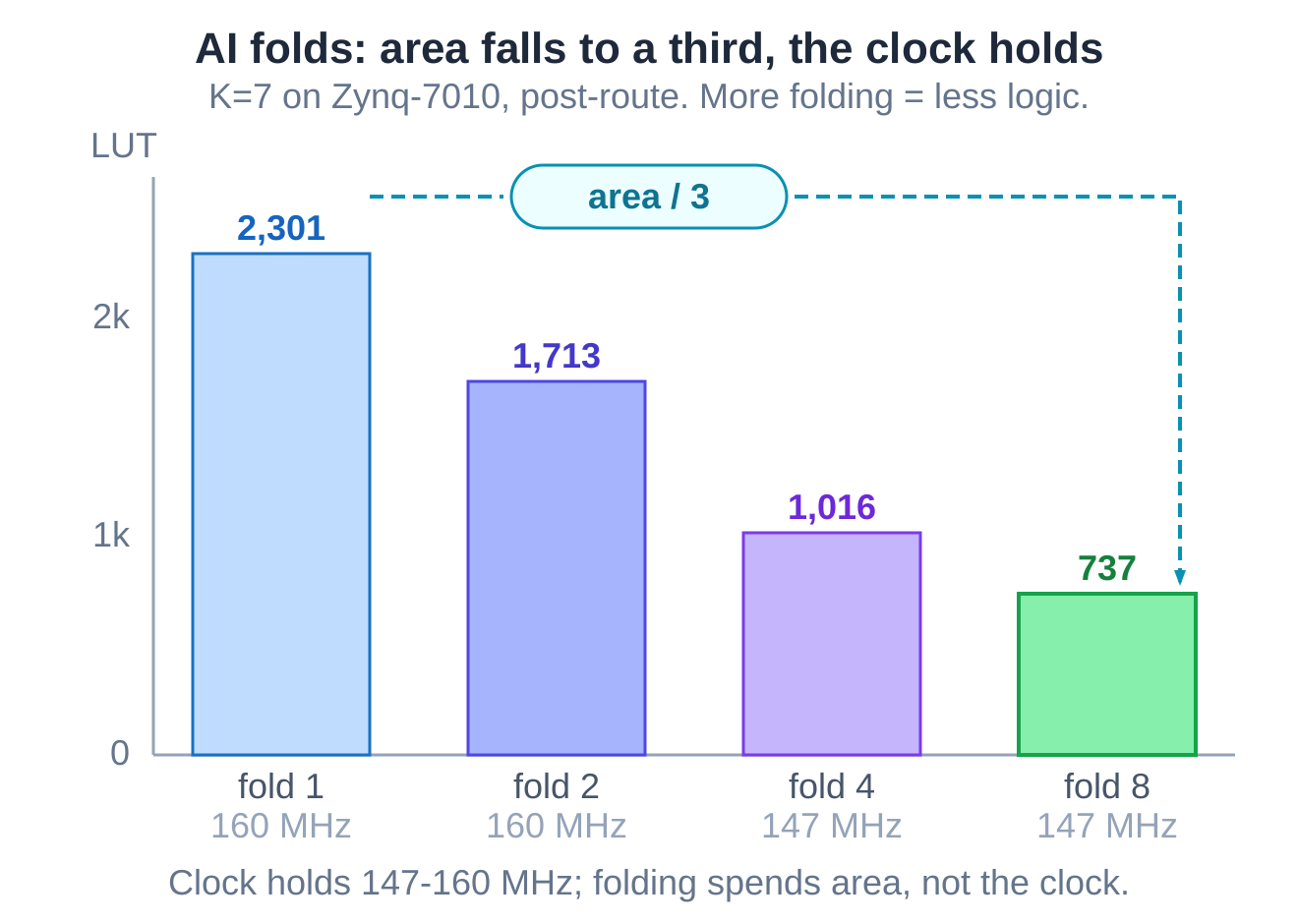
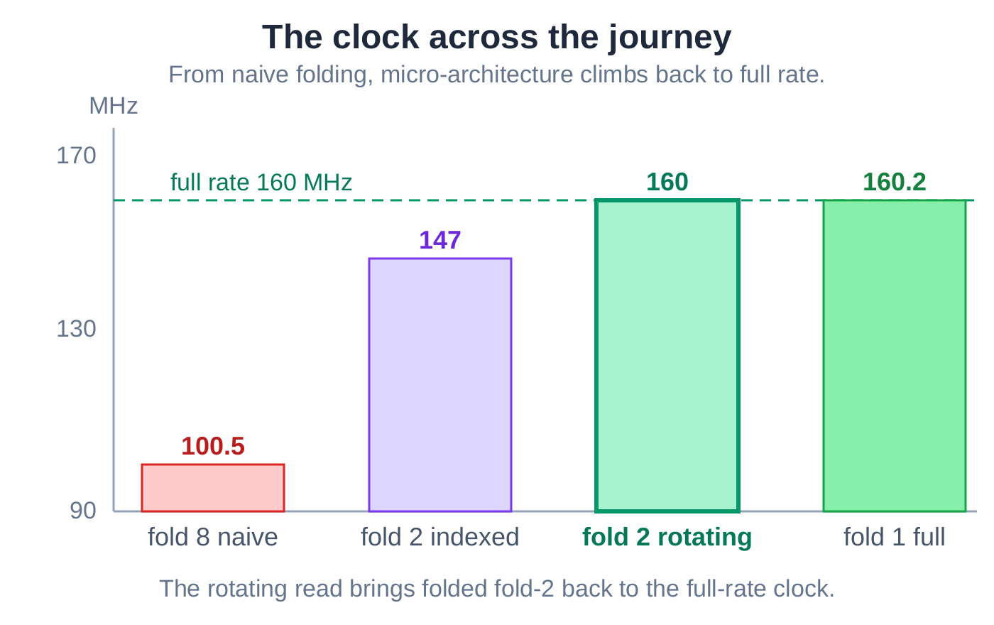
Folding reuses one add-compare-select engine across several clocks instead of building one per state. The AI folded, and the area came down immediately: the constraint-length-seven core fell from about 2,300 logic cells to roughly 740 - close to a two-thirds saving.
Then it measured the clock, and the clock had dropped. It did not stop there.
The diagnosis: folding is not the same as losing the clock
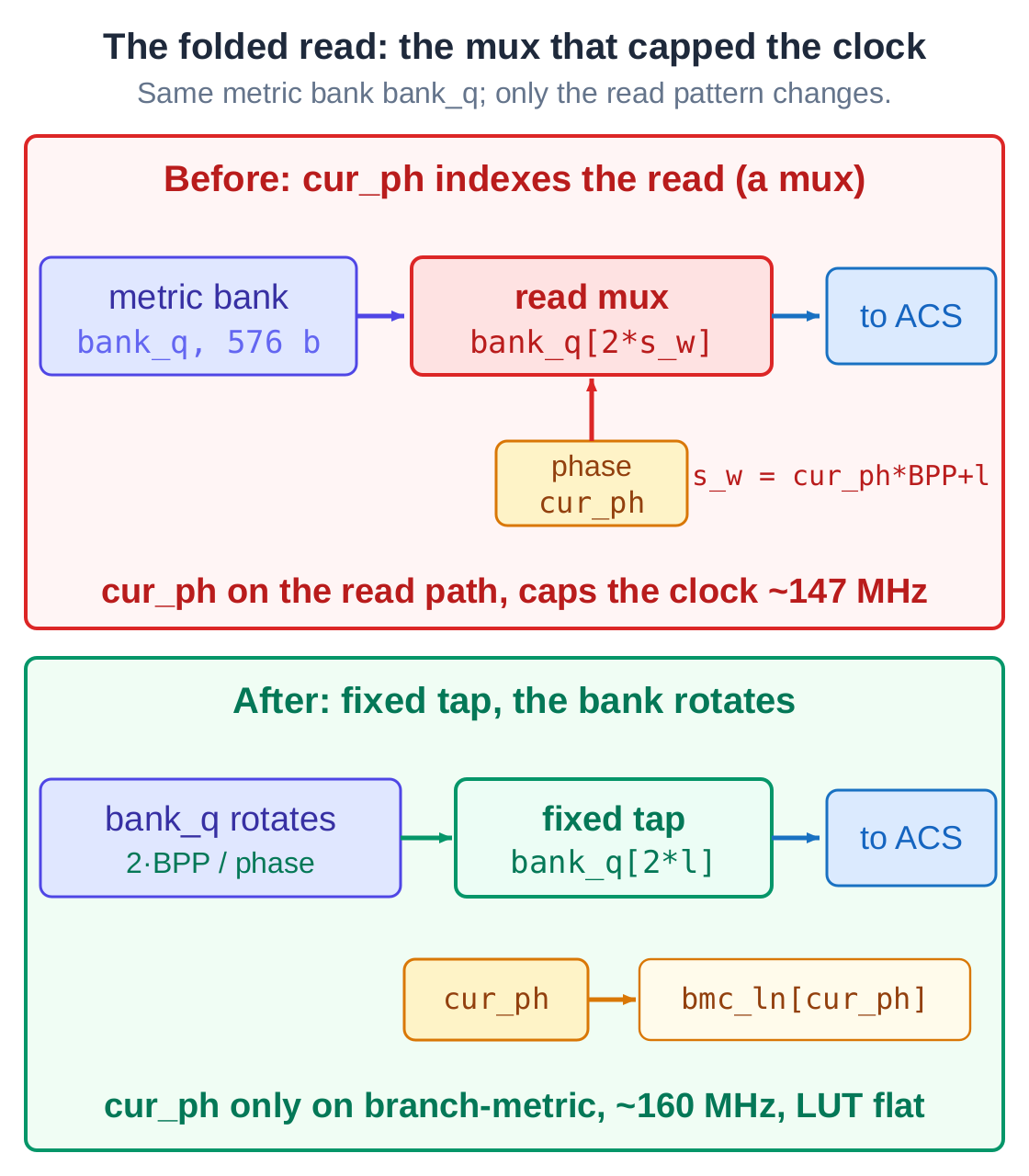
The AI opened the critical path, and the cause had little to do with folding itself. The read microarchitecture was built wrong. After folding, each clock reads a different slice of the storage bank, and the most direct way to write that is to use a phase counter to index a multiplexer. The trouble is that the phase counter landed squarely on the read path feeding the feedback loop - the one path that is already hard to keep fast.
The problem was not folding. It was how that read was built. Change the structure, and the clock comes back.
The fix: rotate the buffer, read a fixed tap
The AI changed the read to a rotation. Instead of a moving index choosing a slice, it reads one fixed, unchanging tap and rotates the bank by one position each phase so the next slice arrives in front of it. That pulls the phase counter off the wide read path entirely - it now only selects the branch cost. The AI measured again: at the same fold factor, the clock climbed from 147 back to about 160 MHz, the logic area was unchanged, and it even shed a few flip-flops.
There is a general rule underneath this. Folding any two-input butterfly forces a data reorder - you cannot avoid it. The only choice is where to pay for it, and here the cost was placed where it is free.
A few more levers
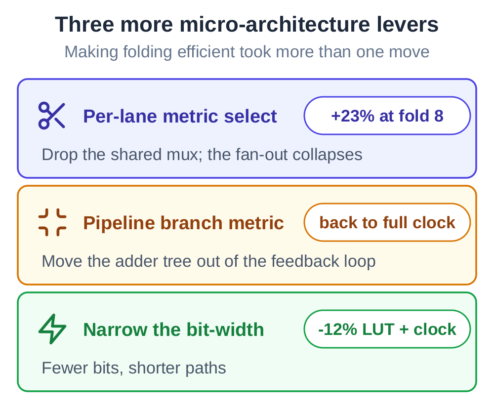
Making folding efficient was not one trick but a string of microarchitecture choices the AI worked out by trying them:
- Splitting the shared branch-cost multiplexer into one per lane drops the fan-out and, at the deepest fold, recovers more than twenty percent of the clock at the heaviest code rate.
- Moving the adder tree out of the way of the feedback loop returns the deep-rate case to full speed.
- Narrowing the arithmetic widths saves more area than folding alone at the lighter code rates, and lifts the clock as a side effect.
A dead-end, kept on the record
The AI also tried a third approach: a double-buffered ping-pong read. It built it, synthesized it, and ran it all the way through place-and-route - not a paper estimate. The result was a regression, about 12 MHz slower than the rotating read. So the AI backed it out.
That negative result is not wasted. It is what makes the final numbers trustworthy: the chosen design won against a real alternative that was measured and rejected, not against a strawman.
A menu, and the receiver that uses it
What the AI produced is not a single point but a menu. Fold less and the design is faster and larger; fold more and it is smaller and slower. The 54 Mbps that 802.11a needs is cleared by both the light folds; the deeper folds are smaller and slower, suited to slow channels where you would rather pack several decoders onto one chip. Every point on the menu is verified and deliverable.
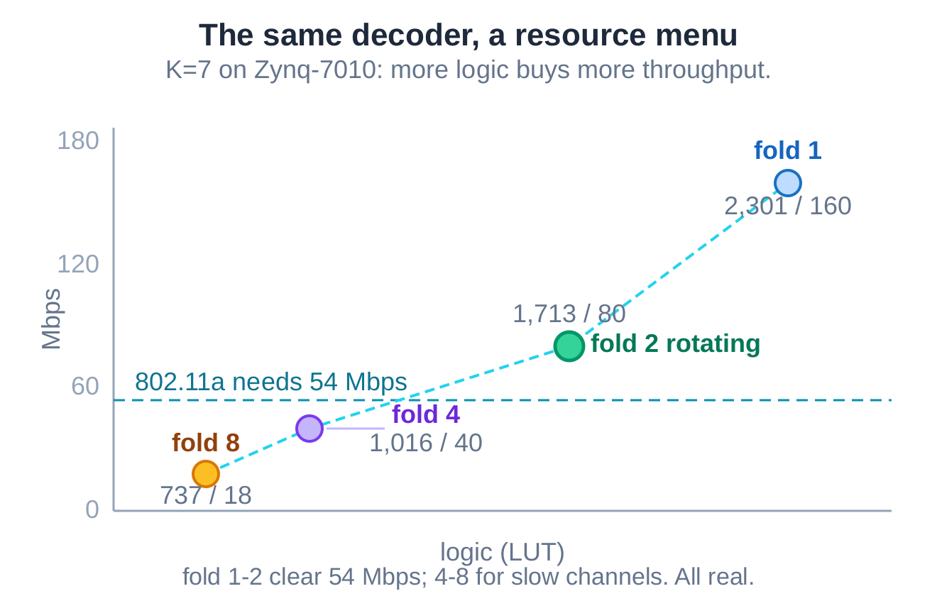
The deployed version is the two-fold rotating-read decoder. It went into a complete 802.11a receiver, was fed raw samples, and recovered the payload with zero bit errors across all eight modulation-and-coding schemes. A microarchitecture that wins on a benchmark only counts once it is inside the real receiver, decoding real samples, with every mode bit-exact.
What the loop was
The final configuration is small and unglamorous: a two-fold decoder that holds the full-speed engine’s clock while occupying only the folded engine’s area, running on a low-cost Zynq-7010. The useful part is the loop that produced it.
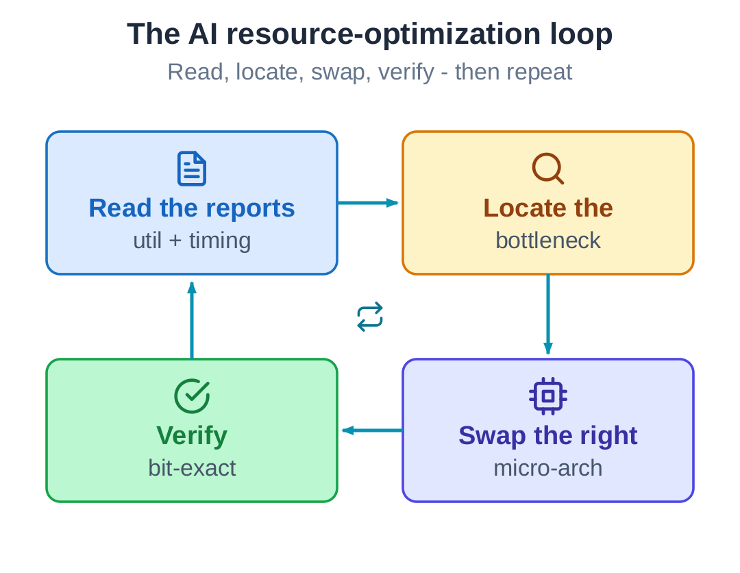
Read the physical constraints, and tell apart a clock lost to folding from one lost to the microarchitecture. Judge correctly: folding is not the same as losing the clock, so put the unavoidable reorder where it costs nothing. Hit a dead-end and back out - the double buffer was measured and rejected, and that is what lets the numbers stand. Verify bit-for-bit: get each change right in the model first, then turn it into hardware, then check it again.
The decoder is replaceable. The loop is the thing worth keeping.