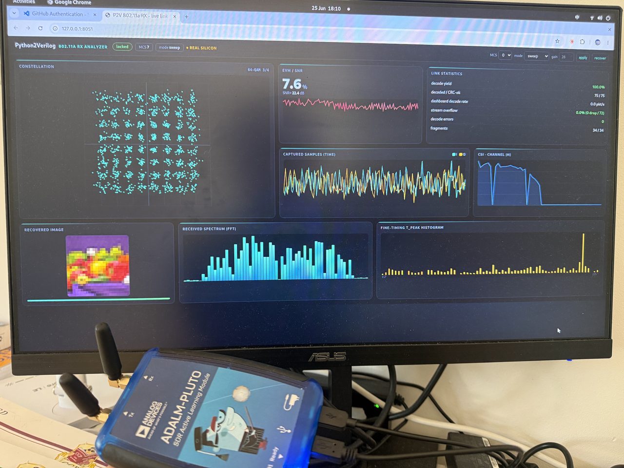
A complete 802.11a Wi-Fi receiver now runs on an ADALM-Pluto, a software radio you can hold in one hand. You can feed it a real over-the-air signal and watch it rebuild a transmitted image, pixel for pixel, with no errors.
There is a catch that makes the story interesting. The receiver did not fit. The full design, plus the radio interface it has to live next to, is larger than the small chip on the board. So the receiver was not built as one block. It was split across two processors, with a third moving data between them, and the split was made without giving up the one thing that matters: every layer still matches the same reference, bit for bit.
It did not fit
The board is built around a Zynq-7010, one of the smallest parts in its family. It has about 17,600 lookup tables of programmable logic, and not much else.
The receiver alone uses about 8,500 of them. The radio interface that has to sit beside it, the part that talks to the analog chip and moves samples on and off the device, uses roughly another 8,500. Add them up and you are over the budget of the chip before anything else. A single monolithic receiver was never going to close.
This is the ordinary situation in real deployment, not a special case. The design that passes in simulation is often a little too big, or a little too slow, for the actual silicon you can afford to ship on. The question is what to do about it without breaking what already works.
Split the work, keep the correctness
The answer was to cut the receiver in two and put each half where it belongs.
The front of the receiver is rate-critical. It sees every incoming sample at full speed: it has to detect when a packet starts, correct the frequency offset between transmitter and receiver, find the exact symbol timing, and run the transform that turns the time-domain samples into the frequency domain. That work has a hard real-time deadline, so it stays on the FPGA fabric, on the radio itself.
Everything after the transform is no longer tied to the sample clock. Estimating the channel, equalizing it out, turning soft symbols into bits, and running the convolutional decoder that fixes the remaining errors: all of that can run on an ordinary host CPU, a laptop connected over USB. The radio’s own embedded processor sits in the middle and does no math at all. Its only job is to move the samples from the fabric, across USB, to the host.
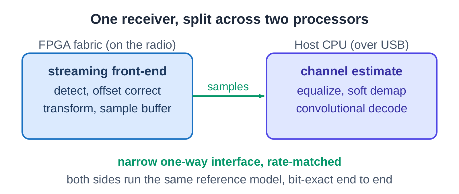
Two things make this split safe rather than risky. First, the cut is placed at the narrowest point in the whole pipeline. After the transform, the data has been reduced to a handful of frequency bins per symbol, so far less has to cross the USB link than the raw sample stream would need. And it only flows one way, fabric to host, with no tight loop reaching back. Second, the FPGA half and the host half are both checked against the same reference model. The boundary between them is not a place where behavior is allowed to drift. It is bit-exact on both sides, so the split receiver computes exactly what a single-chip receiver would have.
One flow, any design
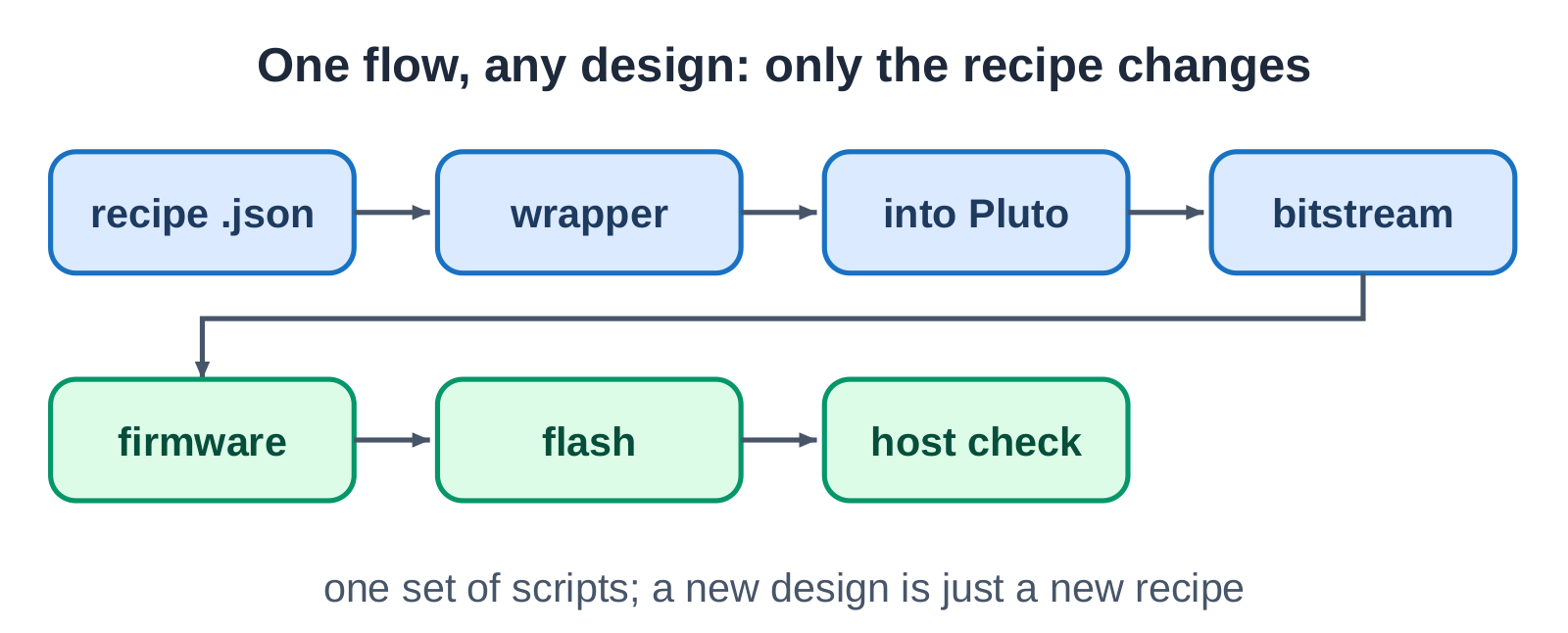
Splicing a generated block into a vendor’s radio design by hand, once, is a weekend of careful work. Doing it for every revision is where projects stall. So the deployment itself is a fixed pipeline, and only its input changes.
A short configuration file describes the design. From there the steps never vary: generate the wrapper that fits the block into the radio’s existing FPGA project, build the bitstream, package the firmware, flash the board, and verify the result on the host. Change the configuration and the same pipeline carries a different design onto the same board. The scripts are written once; a new design is a new input, not a new bring-up.
Bring it up one rung at a time
On a desktop simulator a design either works or it does not, and you can see straight into it. On a real board, almost nothing is visible. If the full receiver is loaded and the screen stays blank, the cause could be the toolchain, the clocks, the sample path, the data movement, or the receiver logic, and there is no obvious way to tell which.
So nothing was loaded all at once. The board was brought up one rung at a time, each rung a test that has to pass on real hardware before the next is attempted. The first rung carries no design logic at all: it just reads back a known counting ramp, which proves the entire toolchain, from build to flash to host readout, is sound. The second rung adds the plumbing: the live sample tap, the clocks, the crossing between clock domains, with still no receiver in place. Only when those two pass does the third rung load the actual sync-and-decode design.
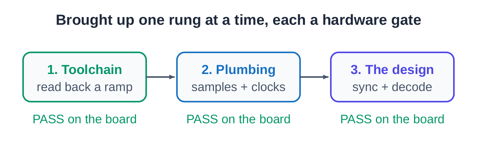
The order matters because a failure on the top rung is unreadable until the lower rungs are proven. Spend the time to light up the toolchain and the plumbing first, and the hard bug, when it comes, has nowhere left to hide.
The proof
The deployed front-end closes timing at about 162 MHz on the fabric of that small chip, with room to spare above the rate the standard asks for, and it fits in under half of the chip’s logic. That leaves the rest of the device free for the radio interface it has to share with.
Then the real test: a live link. Across all eight of the standard’s modulation and coding modes, from the slowest and most robust to the dense 64-QAM, the receiver recovers the payload bit for bit. Over a wired connection it decoded 1,390 packets out of 1,390 across a continuous run, with no errors and no stalls. Moving to two antennas and a genuine over-the-air link, with only the receive gain retuned, it held 99.88 percent: 831 clean packets out of 832, the single miss a real radio-channel event rather than a flaw in the design. The transmitted image comes back whole.
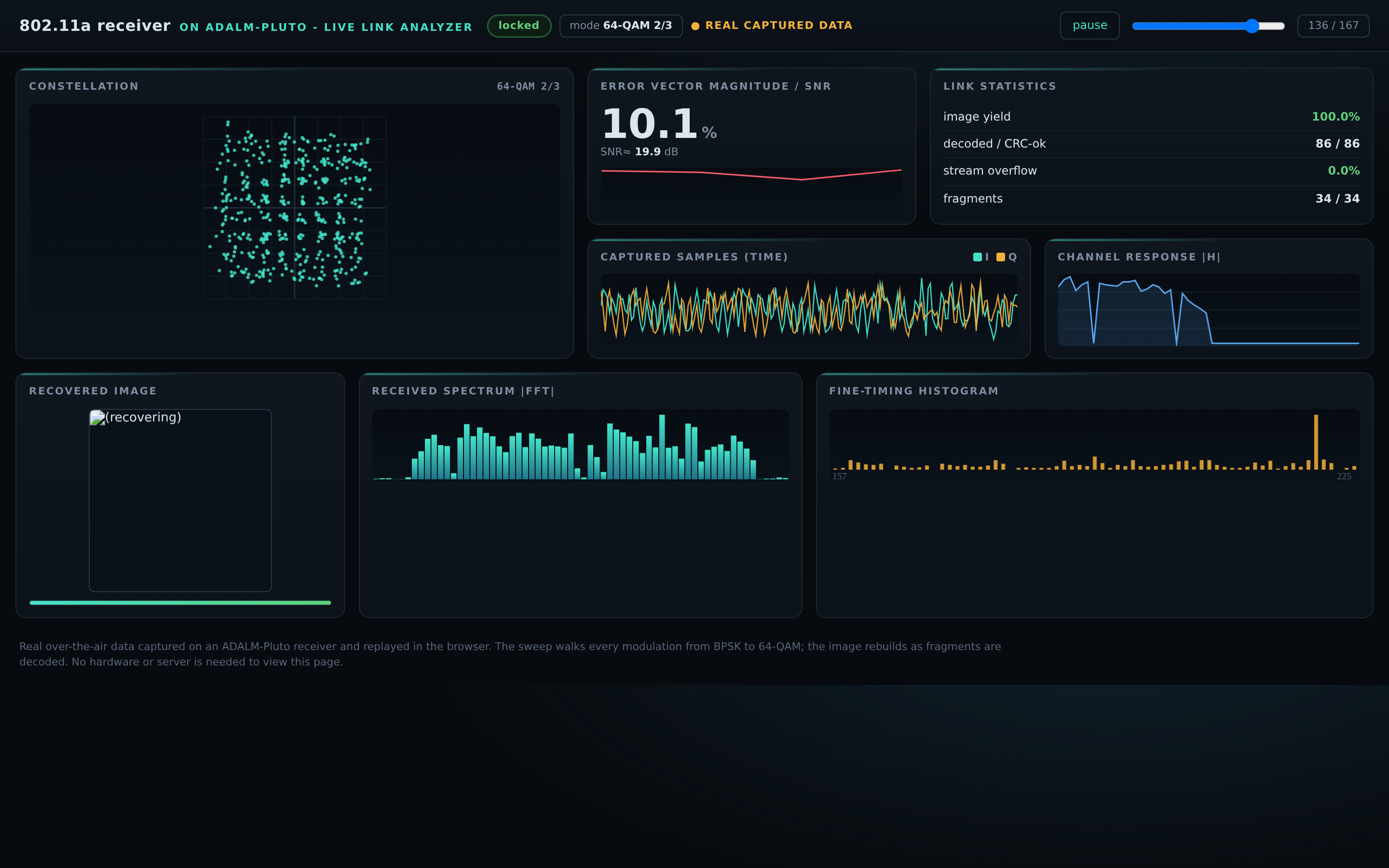
That dashboard is not a screenshot. It replays the real captured data in your browser and rebuilds the image as the packets arrive, with no hardware or install needed. You can open it here: the live link analyzer.
Why it matters
The receiver is one design. The method is the reusable part, and it is the same method any time a design outgrows a single piece of silicon.
Do not partition for its own sake; partition only to clear a ceiling you have actually measured, and shrink each piece in place first. When you do cut, cut at the narrowest point, send the data one way, and avoid putting a tight loop across the boundary, because a loop that crosses the link inherits the link’s delay. Above all, hold every piece to the same reference, so that splitting the work never means splitting the answer. Then bring it up on the real board one rung at a time, and let each rung earn the next.
A receiver that passes in simulation is a result on paper. The same receiver decoding a live signal on a radio you can hold, every mode bit-exact, is the result that counts.
Notes
- Live demo: the over-the-air link analyzer replays real captured data in the browser at algosilicon.com/assets/demos/wlan-pluto-rx.
- Hardware: ADALM-Pluto, built on a Xilinx Zynq-7010 (part xc7z010clg225-1).
- Numbers cited are post-place-and-route timing and resource figures and measured hardware decode runs, traced to the design’s current tool reports.
- A companion post covers how the receiver’s hardware was generated and proven correct layer by layer, before it ever reached a board.